Sep 25, 2026
Stopping Thermal Runaway Propagation: 2 mm Microporous Barrier Solutions for LFP Battery Packs
A barrier-material brief for battery engineers: what a venting cell throws at whatever sits between cells, why organic fillers, mica, aerogel and fibre paper each fail the slot, how a 2 mm inorganic m
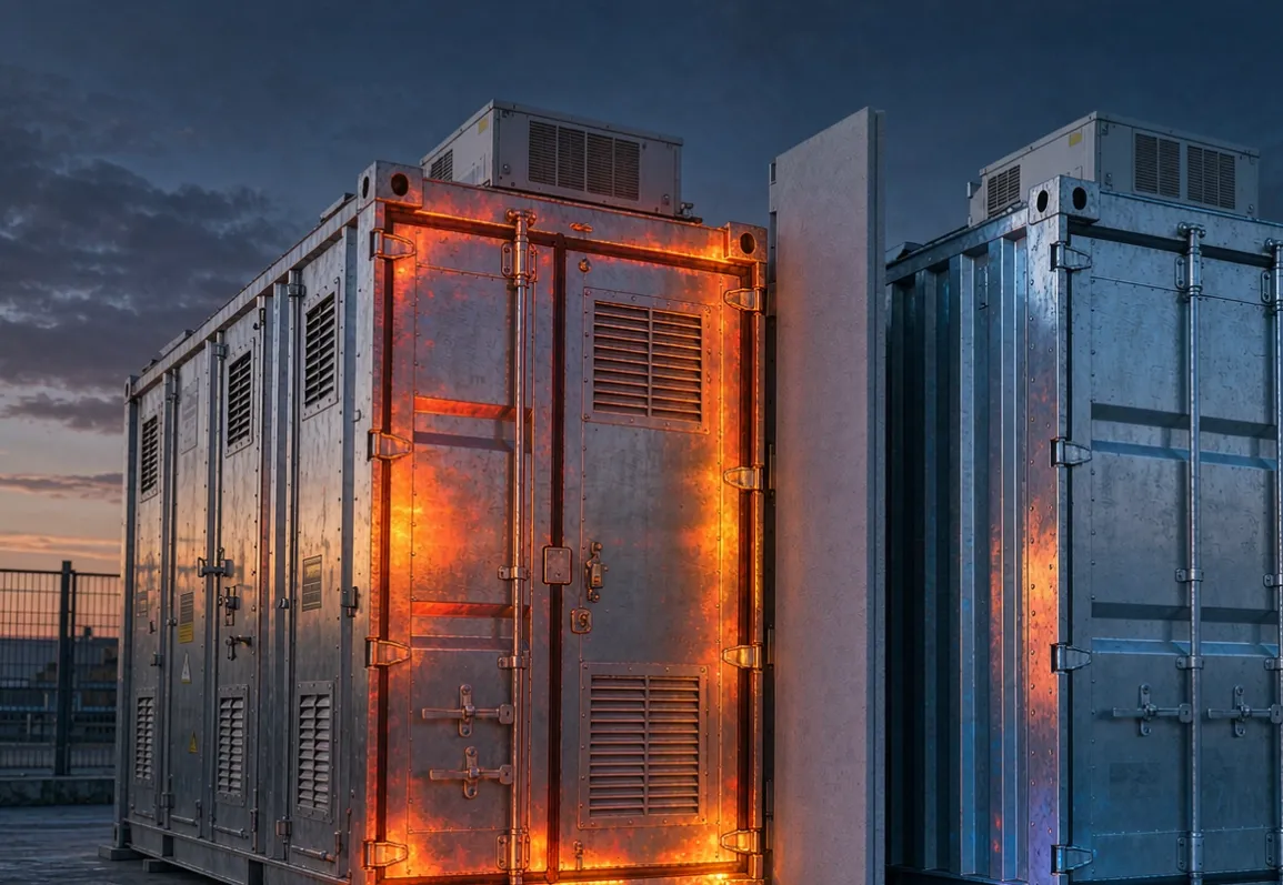
In a grid-scale battery, the question is never whether a cell will fail — fleet statistics settle that argument. The question is whether the failure stays in its slot. Since UL 9540A made propagation a measurable, certifiable property of a pack rather than a promise, the material sitting between cells stopped being packaging and became a safety component with a specification, a test, and a failure mode of its own.
That specification is brutal to write against. The barrier must live in a slot measured in single millimetres, survive a jet of burning electrolyte at 800 to 1000 C without feeding the fire, add nothing toxic to the gas stream the test measures, and still let an automated assembly line run at speed. Very few materials survive all four constraints at once, and the ones that do deserve to be chosen on engineering rather than habit.
What a venting cell actually throws at the barrier
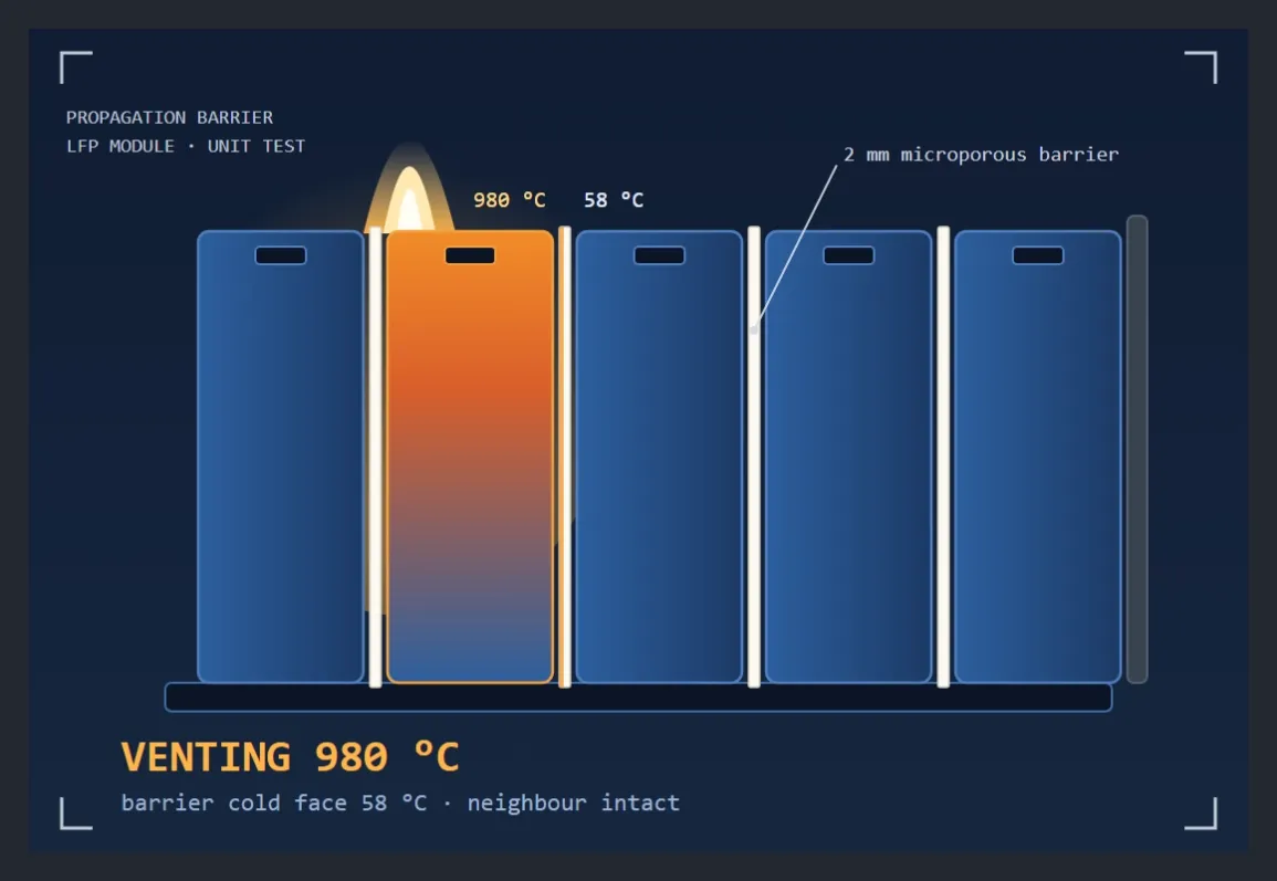
When an LFP cell goes into runaway, the burst disc opens and the event is directional: a jet of hot gas, electrolyte vapour and particulate matter, at 800 to 1000 C, lasting minutes. The barrier around that cell sees three heat paths at once.
Radiation dominates first. At 1000 C, radiative transfer across even a small gap is enormous, and it starts the instant the jet appears — before any gas has touched the barrier face. Conduction through anything that touches follows: the barrier, the busbars, the module frame. And convection by hot gas comes third, concentrated where the vent actually points.
The job of the barrier is to hold the cold face below the neighbour's venting threshold for the duration of the event — the five-to-ten-minute window in which either the energy is absorbed or the module row is lost. Whether the cold face stays there is a function of the material's thermal properties in both steady-state and transient terms, and this is where most cheap fillers quietly fail: they look acceptable in a steady-state datasheet column and lose the event in the first two minutes.
Why the usual fillers run out of space
The spacing budget is unforgiving. Cell-to-cell gaps run 1 to 3 mm in dense LFP modules; module-to-module gaps reach 5 to 10 mm. Everything that goes into those gaps competes on four axes at once:
Organic and FR-laminated composites add fuel, char, smoke and dripping — precisely the species the UL 9540A gas analysis is designed to catch. Many pass a coupon flame test and fail the unit-level event.
Mica sheet survives temperature but conducts several times better than microporous material at thicknesses that fit, and it handles badly on automated lines — it cracks, it flakes, and every crack is a short path through the barrier.
Aerogel blankets insulate well but arrive fragile, shed dust, and rely on binders that can burn out at the very temperatures the event delivers.
Ceramic fibre papers lack the strength to be inserted, clamped and vibrated without damage.
What the slot actually wants is a thin, inorganic, dimensionally stable sheet that is strong enough to be assembled like a component and insulating enough to be treated like a firewall.
The microporous option in a 2 mm slot
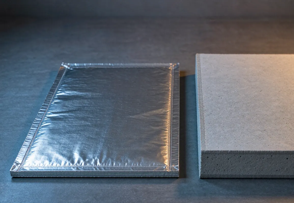
A 2 mm sheet of SLM-1200 class microporous board meets that description on every axis, and the reasons are worth understanding rather than quoting.
It is inorganic through its thickness — no fuel content, no dripping, no smoke contribution, and nothing for the gas analysis to find. It survives direct impingement at 1000 C without melting or shrinking past its specification, because its classification temperature sits far above the event. Its pore structure is opacified against infrared, which matters more than any steady-state number in this application: at 1000 C, radiation is the first and fastest heat path across a thin barrier, and a material that is opaque to it removes that path entirely. Its steady-state conductivity — the honest version of which lives on the conductivity curve at real mean temperatures rather than in the headline figure — is a fraction of mica at the same thickness. And its low thermal diffusivity means the cold face climbs slowly even before steady state is reached, which is exactly the behaviour a five-minute event rewards.
Two practical properties matter to the pack line as much as the thermal ones. The board is a strong electrical insulator — an inorganic dielectric across the cell faces it separates. And it is light: at roughly 0.5 kg per square metre in a 2 mm sheet, a full interleave of barriers adds less mass than one cell lid.
One honesty note belongs in the design file: a datasheet does not certify a pack. The barrier gives the pack a defined thermal resistance where there used to be hope, and the pack-level UL 9540A test proves what that is worth. The material choice is what makes that test survivable.
Design details that decide the test
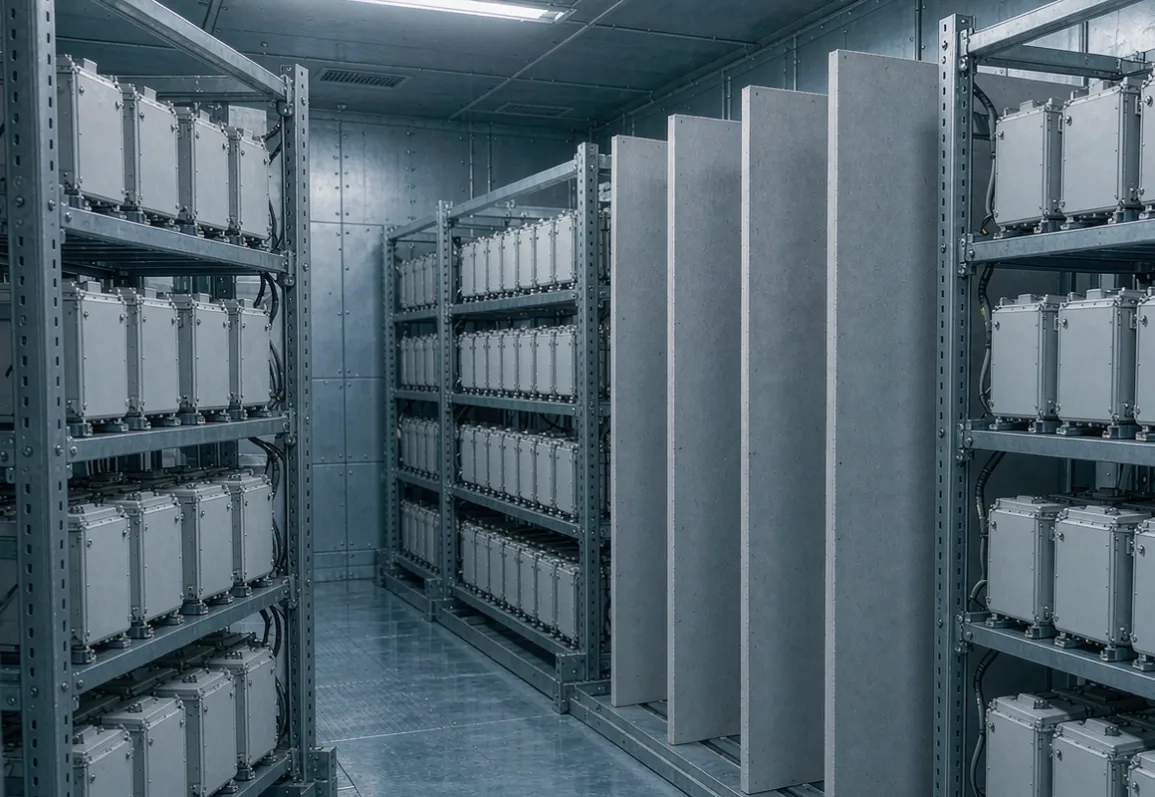
Respect the vent. The barrier layout must route, not block, the burst disc's gas path. A barrier that walls a cell in completely converts a directed jet into pressure with nowhere to go. Interleave barriers between cells combined with designed vent channels at the tops of modules outperform a naive full enclosure — the gas leaves, the radiation does not.
Kill the bridges. Busbars, standoff bolts and module frames cross every barrier layout, and each one is a thermal short circuit with a copper core. Shaped barriers — die-cut notches, busbar slots, moulded standoffs — keep the metal from touching across the insulation plane. That is a fabrication question as much as a material one, and it is why how SLM nano insulation boards are made matters to a battery engineer: the parts arrive cut to drawing, not as sheets someone cuts on a table beside the assembly line.
Assemble like a component. The board's stiffness and thickness tolerance are what let it run through automated insertion without jamming, cracking or leaving bare spots at the edges. Parts that arrive chipped or wet are parts that will underperform in exactly the event they exist for — which is why the incoming inspection protocol applies to battery barriers with the same force as to refractory linings, and why the questions worth asking a barrier supplier before the first PO are the ones in the supplier audit checklist. On the line itself, the handling rules in the storage and cutting field guide — support the sheet, protect the edges, never drag it — are written for refractory crews but apply verbatim to barrier kits. Machining dust from any inorganic board should be vacuumed, not blown, before modules are closed up.
Where the same physics shows up next
The module-to-module firewall — the 5 to 10 mm wall between battery rows, or between the battery compartment and the cabin in a commercial vehicle — is the same problem with a thicker budget, and microporous board fills it the same way. At the other end of the temperature scale, the same material family solves the opposite brief: keeping a 1200 C thermal battery inside a shipping envelope, as the LDES vessel wall guide sets out. One material class, two certifications, one supply chain.
For the industrial and utility-scale view of high-temperature insulation — including what these boards do behind refractory in continuous service — the anchored ladle back-up assembly page shows the build-up in place.
If you are designing barriers into a pack or module and want die-cut parts, thickness options and honest thermal figures to design against, write to us with your slot dimensions and the event spec you are testing to.
Questions on grades, die-cut parts or barrier layouts: sales@slmthermal.com