Sep 23, 2026
How to Keep Vessel OD Within 2.6 m While Storing 1200 C: Optimizing LDES Wall Thickness
A wall-thickness method for high-temperature thermal battery vessels: the three budgets that size the wall (transport envelope, storage volume, shell temperature), why conventional refractory and fibr
A thermal battery wall has to satisfy three budgets that fight each other, and the transport envelope usually wins the argument. The vessel must move inside a standard container or down a public road; the shell must stay cool enough to touch and cool enough not to cook its own bearings; and every millimetre spent on insulation is a millimetre taken away from the solid medium that actually stores the heat your customers are paying for.
That last point is easy to underestimate in the early design phase. On a 2.2 m diameter vessel with a 4 m tall core, each additional 10 mm of wall thickness costs roughly 0.28 cubic metres of storage volume — multiplied by the number of vessels in the array, that is revenue capacity traded away for insulation. Getting the wall stack-up right is therefore not a detailing exercise; it is one of the decisions that sets the economics of the whole system.
This article walks through the wall-thickness logic the way the thickness sizing guide does for ladles, but aimed at the specific constraints of high-temperature LDES vessels: a hard outer-diameter limit, a 1200 C class core, and a floor that has to carry the entire medium stack on top of the insulation.
The three budgets that size the wall
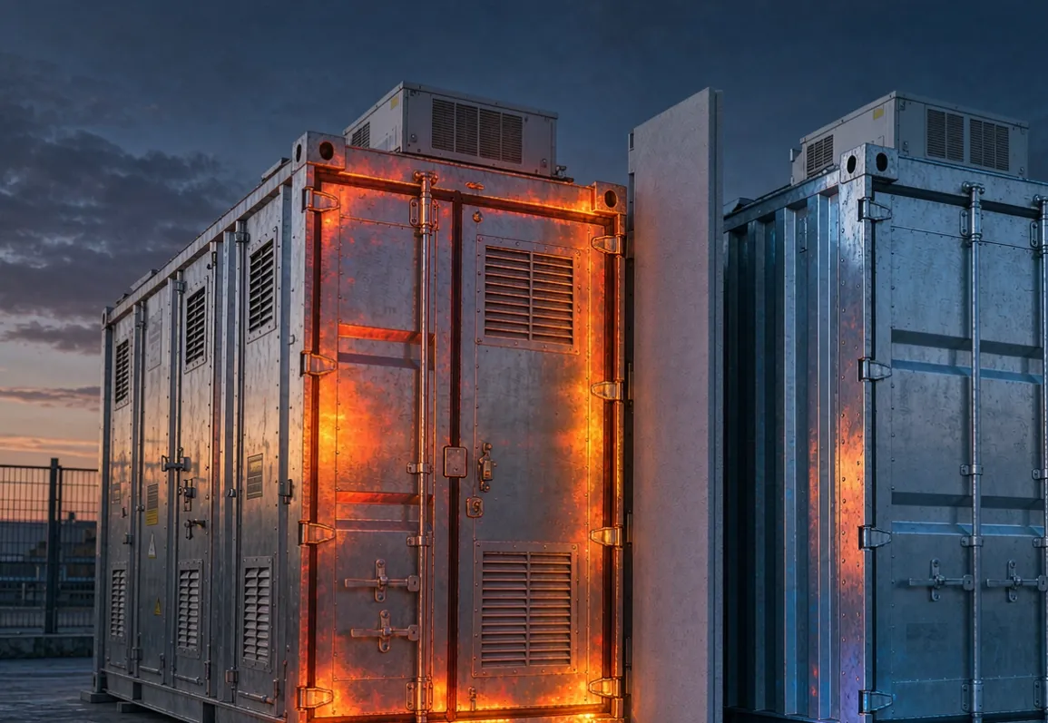
The transport envelope. A standard 40 ft container accepts cargo up to about 2.35 m wide; most road gauges allow an outer diameter around 2.5 to 2.6 m for anything that wants to move without special permits. If the vessel is built on-site the constraint relaxes, but modular factories — which is most of the LDES industry right now — ship their thermal cores complete. The wall budget is whatever is left after the core diameter and the shell plate.
The volume economics. Every millimetre of radial wall is bought twice: once in capex, once in lost medium volume. This is why the correct comparison between insulation options is never price per square metre — it is price per cubic metre of storage capacity preserved. A cheap, thick insulation layer quietly destroys more value than it saves.
The shell temperature target. 60 to 70 C at the outer surface is the usual brief: safe to touch in passing, gentle on painted steel, benign for instrument wiring and pipe penetrations, and low enough that standing losses stay a rounding error rather than a line item. The shell temperature is an output of the wall design, and it has to be met at end of campaign, after the insulation has done all the shrinking it is ever going to do.
Why conventional walls stop fitting
Run the numbers with traditional materials and the envelope closes fast.
Dense castable or firebrick conducts at 0.5 to 1.5 W/(m·K) at operating temperature. Holding the heat flux through the wall to roughly a kilowatt per square metre across a 1100 degree drop needs somewhere between 400 and 700 mm of it. Lighter insulating firebrick and conventional fibre back-ups get that down to the 150 to 250 mm class — still most of a 2.6 m budget gone before the hot-face liner and the shell plate are paid for.
Ceramic fibre adds a second problem that pure conductivity numbers hide: it shrinks and it compacts. Under the static load of a solid storage medium, fibre modules consolidate, and every point where the insulation has thinned is a thermal short circuit. What the material does under load and over time is a datasheet question — the permanent linear change line on a proper data sheet is where that answer lives, and it should be read against the operating temperature the wall will actually see in the bottom course, not the average.
Where the microporous layer goes in the stack-up
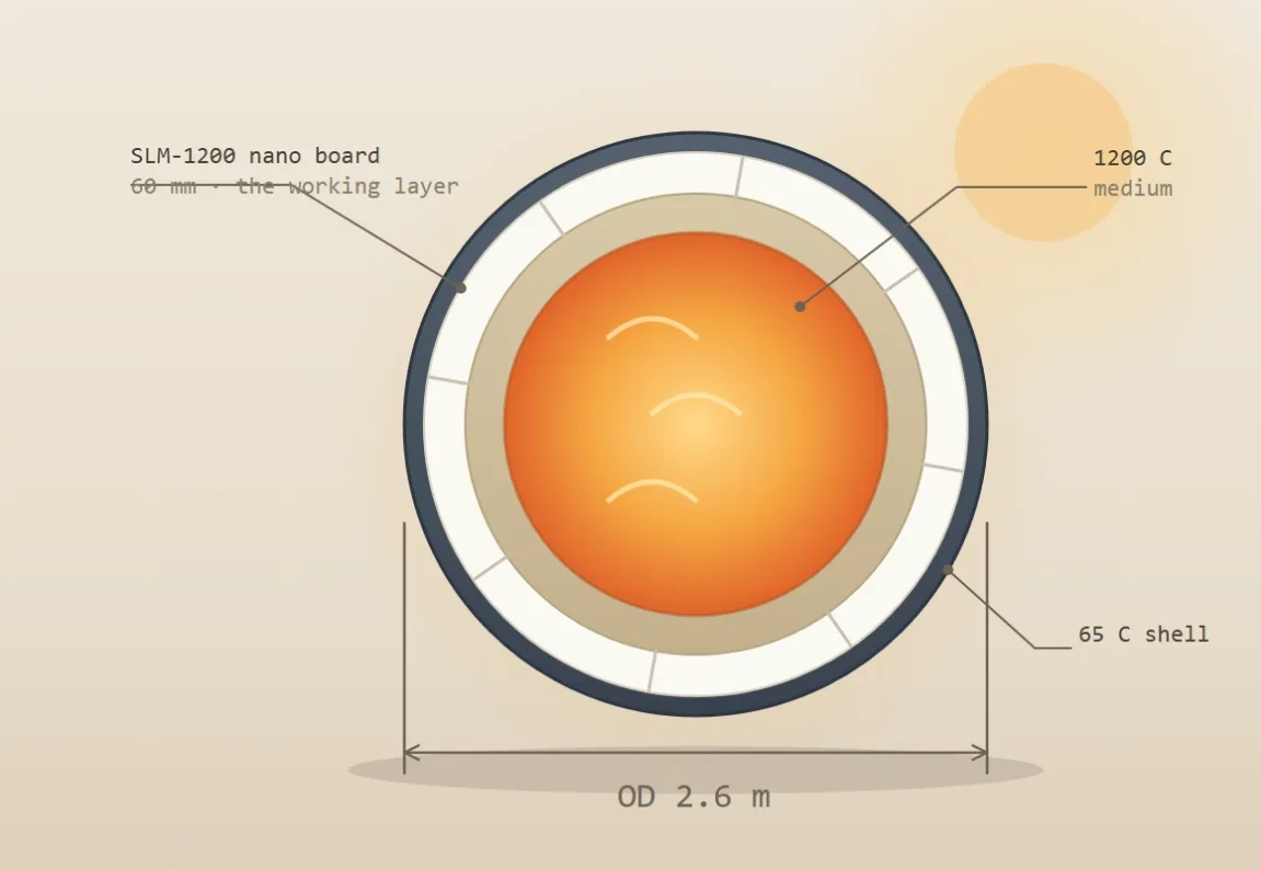
The stack-up that fits a 2.6 m envelope is, from the inside out:
A hot-face liner appropriate to the medium — dense refractory or a metal/graphite liner for solid sensible-media cores. This layer takes the abrasion and any chemical aggression; it is not doing the insulating.
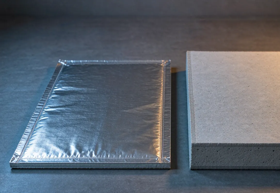
A microporous nano insulation board back-up doing nearly all the thermal work. At 1200 C class core temperatures the grade to specify is SLM-1200; its conductivity at high mean temperature sits an order of magnitude below the dense refractories around it. Two datasheet lines matter more than the rest: the conductivity curve at real mean temperatures — the headline figure is always the room-temperature one, and the honest number is on the conductivity curve — and the shrinkage limit discussed above.
A small air gap or low-grade filler and the steel shell, sized for structure, not for insulation.
The arithmetic that makes this fit: at an effective mean-temperature conductivity around 0.045 W/(m·K), a 50 to 60 mm microporous layer holds the same kilowatt-per-square-metre flux that needs 400 to 600 mm of dense refractory or 150 to 250 mm of conventional insulating back-up. The insulation layer shrinks from most of the wall budget to roughly a quarter of it, and the saved radius goes back to the medium where it earns revenue.
That ratio is also the honest answer to "why not just use more cheap fibre": the envelope does not price materials per millimetre, it prices the whole diameter.
The floor: carrying tonnes at temperature
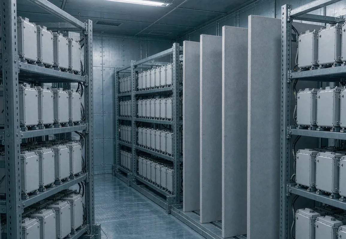
The wall gets most of the design attention, but the floor is where LDES vessels differ most from every other microporous application — the entire medium stack, tens of tonnes in a container-scale unit, bears down through the base insulation.
Fibre blankets fail here by consolidation. Microporous board does not, provided two rules are respected. First, respect the compressive specification: the board survives defined loads at defined deformation, and the base course design should keep working stress well inside that envelope with a spreader plate distributing the medium's footprint. Second, keep point loads out of the insulation entirely — legs, risers, and heater penetrations should land on structure that bypasses the thermal layer, not through it.
The base insulation is also the hottest, most loaded insulation in the vessel, which makes it the layer to inspect first if the shell tells you something is wrong.
Joints and penetrations: where the arithmetic leaks
A wall design that is exact on paper loses to workmanship unless the joints are engineered with the same seriousness as the layers. The rules are the same ones steel linings live by — stagger the courses so no through-path exists, close the gaps that geometry forces, and treat every penetration as a designed detail rather than a field improvisation. They are set out in the joint and gap control article, and for a cylindrical vessel the practical shortcut is to stop cutting on site altogether: CNC-machined board kits — curved segments, notched boards around penetrations, numbered per position — turn the vessel wall into an assembly job. That is how SLM nano insulation boards are made and supplied for shaped linings, and it removes most of the fit-up error a startup's first vessel crew would otherwise invent.
Verify the wall, then keep verifying it
After commissioning, the wall announces its real performance on the shell. An IR survey — same method as the performance verification guide — maps hot streaks to specific courses and penetrations, and the survey images belong in the vessel's file next to the batch paperwork from the incoming inspection. LDES vessels live for decades; the wall file you start with unit one is what makes unit fifty's warranty conversations short.
Putting the 2.6 m together
One indicative stack-up, for orientation rather than specification: a 2.2 m diameter solid-media core, an 80 mm hot-face liner, a 60 mm SLM-1200 microporous layer, a small air gap and 15 mm shell — roughly 200 mm of wall, a 2.6 m outer diameter, a shell in the low sixties Celsius, and standing losses near the kilowatt-per-square-metre class. Move the same core to conventional back-up materials and the same brief no longer fits the same truck.
If you send us your core diameter, medium temperature and the envelope you are designing against, we will return a stack-up with the numbers filled in — including the ones the datasheet headline will not tell you.
To see what a completed back-up assembly looks like in section, the anchored ladle back-up assembly page shows the build-up in place.
Questions on grades, wall stack-ups or CNC kits for a vessel program: sales@slmthermal.com