Sep 12, 2026
How to Specify Nano Insulation Board Thickness: A Practical Sizing Method
A practical method for sizing a microporous nano insulation back-up layer — the three constraints that actually set the thickness, the steady-state calculation with a worked example, a shell-temperatu
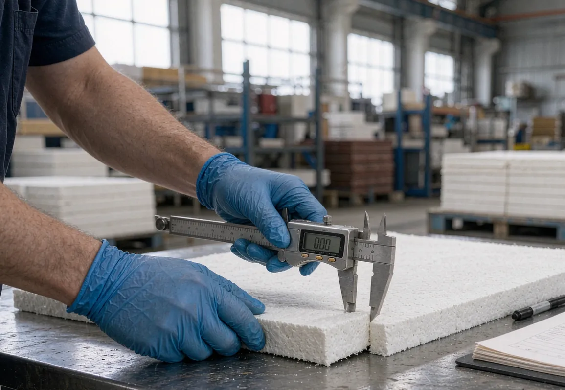
The most common question we get from plant engineers is deceptively simple: how thick should the back-up layer be. Designs built on high-strength nano insulation boards usually settle between 25 and 50 mm, but that range is a result, not a rule. The honest answer is that thickness is not a catalogue choice — it is the output of a thermal design that has to satisfy three constraints at once. Pick it by habit and you will either overspend on material you do not need, or you will run a shell hot enough to fail the energy audit.
This guide gives you the method, a quick reference table you can sanity-check against, and the four mistakes that invalidate most sizing attempts.
Why "thicker is better" stops being true
Adding insulation reduces heat flow, and reducing heat flow lowers shell temperature. That part is linear enough. But the relationship between thickness and shell temperature is one of sharply diminishing returns: the first 25 mm does most of the work, and by the time you are past 50 mm you are buying very few degrees for quite a lot of money and radial space.
Meanwhile every millimetre you add to the back-up layer is a millimetre taken from the working lining or from the ladle's internal volume. On a campaign-limited ladle, that trade has a real cost.
The three constraints that actually set the thickness
1. Maximum allowable shell temperature
This is usually the binding constraint and it has two drivers:
Safety and equipment. Shell temperatures above roughly 350 C accelerate shell distortion, damage adjacent equipment and create a burn hazard on the ladle deck. Most plants set an internal limit between 250 and 300 C.
Energy. Every degree of shell temperature is radiated heat you paid for. In the ROI calculation we published, a 25 C shell drop on a 130 ton ladle was worth roughly 60 to 90 kWh per heat.
2. Working lining back-face temperature
This one is counter-intuitive and often missed. A better back-up layer reduces heat flow, which makes the temperature gradient across the working lining shallower — so the back face of the working lining runs hotter, not cooler.
That is normally beneficial: lower thermal gradient means lower thermal stress and less spalling. But it has a limit. The back face of the working lining must stay below the temperature at which that material starts to soften or creep under load. On magnesia-carbon systems this is rarely the binding constraint; on some alumina and high-alumina working linings it can be.
If you are pushing a thin working lining hard, check this with your lining designer before you commit to a thick back-up layer.
3. Available radial space
The ladle shell diameter is fixed, so the annular space is shared between working lining and back-up insulation. Adding 25 mm of back-up either:
reduces the working lining by 25 mm, which shortens campaign life, or
reduces the internal volume, which reduces the tonnes per heat.
On a 130 ton ladle, 25 mm off the working lining can cost more campaign life than the energy saving is worth. Where mean service temperature runs above 1000 C, SLM-1200 at a reduced thickness often beats a thicker layer of a lower-rated grade — the SLM-1000 vs SLM-1200 comparison guide walks through that trade-off in detail.
The sizing method
For steady-state one-dimensional heat flow through a composite wall:
q = (T_steel − T_ambient) / (d_work/λ_work + d_ins/λ_ins + R_external)
Where:
q is heat flux in W per square metre.
d_work and d_ins are the working lining and insulation thicknesses in metres.
λ_work and λ_ins are the thermal conductivities at their respective mean service temperatures — not the room-temperature values on the data sheet, which are much lower and will make your calculation optimistic.
R_external covers the steel shell and the outside film coefficient; about 0.04 m²K/W is a reasonable planning figure for a ladle in still air.
Solve for the insulation thickness that brings the shell temperature to your target, then check constraint 2 and constraint 3 above.
A worked example
For a 130 ton ladle, steel at 1600 C, ambient 30 C:
Working lining: 150 mm magnesia-carbon, λ ≈ 4 W per m·K at mean temperature.
Back-up: an SLM-1000 class nano board, λ ≈ 0.07 W per m·K at 600 C mean.
External resistance: 0.04 m²K/W.
At 50 mm back-up:
Insulation resistance: 0.05 / 0.07 = 0.71 m²K/W.
Working lining resistance: 0.15 / 4 = 0.04 m²K/W.
Total: about 0.79 m²K/W.
Heat flux: 1570 / 0.79 ≈ 1,990 W per square metre.
Shell temperature: 30 + 1990 x 0.04 ≈ 110 C on the calculation, and typically 200 to 260 C in service once anchor bridges, joints, shell stiffeners and the slag-line region are accounted for.
That gap between the calculation and the real shell temperature is normal and important — it is the subject of the next section.
Quick reference: what thickness buys you
For a typical ladle with a 150 mm working lining, these are the ranges we see in service. Use them as a sanity check, not as a design.
| Back-up thickness | Typical shell temperature | Marginal gain | |---|---|---| | None | 350 to 420 C | — | | 25 mm | 280 to 320 C | about 70 C | | 50 mm | 230 to 270 C | about 45 C | | 75 mm | 210 to 240 C | about 25 C |
The pattern is the point: 25 to 50 mm is where the value is. Going from 50 to 75 mm buys roughly 20 to 30 C for 50 percent more material and 25 mm of radial space. On most ladles that trade does not pay.
Where the simple method breaks down
Four effects make real shells hotter than the calculation, and all four are worth designing around:
Anchor thermal bridges. Steel studs through the board are a direct conductive path to the shell. Non-conductive ceramic washers under the anchor head are not optional if you want the calculated shell temperature to be achievable.
Joint gaps. Every butt joint is a gap. Staggered courses and tight 1 to 2 mm joints keep these short and sealed. The installation guide covers the layout that makes this work.
Compression under load. Microporous board compresses slightly under anchor preload and under the weight of the courses above. Over-tightening an anchor to "make it solid" crushes the board locally and creates a thin spot — and a thin spot is a hot spot.
The slag line and the bottom cone. Both run hotter than the mid-wall and both are usually where the working lining is thinnest. Size for the worst region, not the average.
Common specification mistakes
Using room-temperature conductivity. Nano board conducts significantly more at 600 C than at 25 C. Always size with the value at mean service temperature.
Specifying thickness without specifying density. A low-density board at the same thickness performs differently from a higher-density one, and it also compresses differently. Specify both, and verify both on arrival — the incoming inspection routine shows how.
Ignoring the grade boundary. A board rated for 1000 C continuous service that sees 1100 C will shrink, open its joints and stop performing long before its campaign ends. Where temperatures are marginal, move up a grade rather than adding thickness.
Copying a competitor's specification. Their working lining thickness, shell design and campaign length are all different from yours. The five buying mistakes guide covers why copied specs so often disappoint.
When to go thicker, and when not to
Go thicker when:
The shell temperature limit is driven by safety or by adjacent equipment, not by energy cost.
The ladle has generous radial space and the working lining thickness is not the campaign limit.
Service is continuous rather than cyclic, so the steady-state calculation is actually representative.
Do not go thicker when:
You are campaign-limited by working lining thickness — spend the space on the working lining instead.
The shell is already at 230 C or below; further thickness mostly buys material cost.
Shell distortion is the real problem. That is a mechanical issue with the shell, not an insulation thickness problem.
Getting a number for your ladle
Send us your shell diameter, working lining type and thickness, steel temperature, target shell temperature and campaign length. We will run the calculation against the anchored ladle back-up assembly you are using and return a recommended thickness and grade, with the shell temperature you should expect in service rather than on paper.
For background on why density and thickness interact the way they do, see How SLM nano insulation boards are manufactured.
— The Suleiman Refractory Engineering Team