Oct 25, 2026
Reheating and Heat-Treatment Furnaces: Why the Backup Lining Sets Your Shell Temperature
A reheating furnace loses only 4 to 8 percent of its fuel through the walls, so wall insulation is not the biggest energy saving available - it is the only one you can make with a lining change alone,
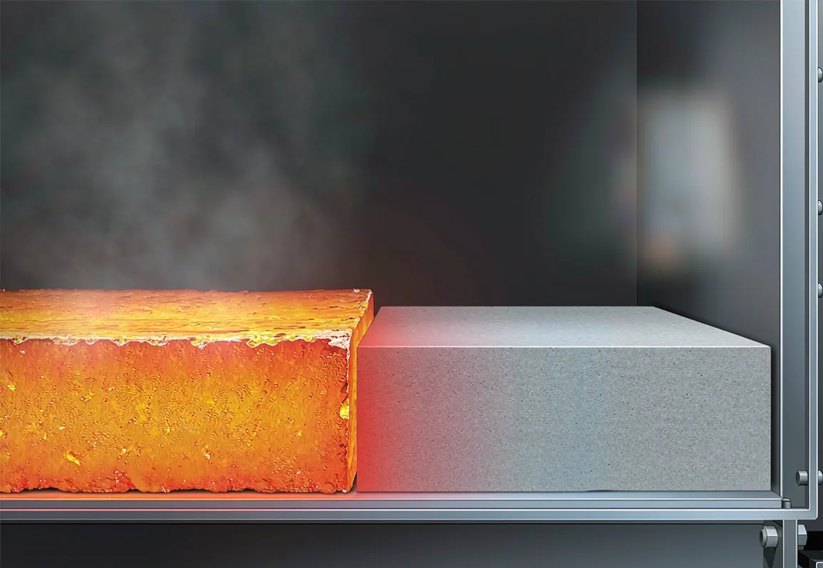
A reheating furnace loses only 4 to 8 percent of its fuel through the walls. The flue gas takes 25 to 40 percent, the water-cooled skids take 3 to 9 percent, and the doors take 2 to 5 percent. So the honest opening line of any furnace-wall proposal is: this is not where your biggest energy saving is. It is, however, the one loss you can fix without touching the process, the combustion system, or the product. And the number it controls — shell temperature — is a safety, maintenance and compliance liability that the other losses are not.
This article is for the engineer or owner's engineer specifying the lining of a reheating, annealing, normalizing or tempering furnace. It sets out what the wall actually loses, why shell temperature is the number that matters more than the fuel, how a microporous nano insulation board performs as the backup layer behind the working refractory at real furnace temperatures, three measured retrofits, a step-by-step sizing method, and the mistakes that turn a good specification into a hot, cracked shell. Conductivity figures are taken from manufacturer datasheets and are labelled as such; shell-temperature limits are taken from national energy-conservation guidance and are cited; figures that could not be located in a published source are marked as such.
What the wall actually loses
The single most useful fact is the loss split. For a typical walking-beam or pusher reheating furnace, the energy balance runs roughly like this (industry energy-balance models, cited in the references):
| Loss component | Share of fuel input | |---|---| | Flue gas (sensible + excess air) | 25–40 % | | Water-cooled skids / hearth tubes | 3–9 % | | Wall and roof (steady-state) | 4–8 % | | Doors, openings, charging zone | 2–5 % |
Two consequences follow. First, a wall-only retrofit recovers part of that 4–8 percent — call it 1.5 to 4 percent of total fuel — not the whole furnace. Anyone promising a 30 percent furnace saving from wall insulation alone is selling something else. Second, the wall is the only one of these you can address with a lining change alone, with no process risk. The flue-gas and skid losses need heat-exchangers, combustion tuning or skid redesign. The wall needs insulation.
The application map places furnace walls in the 800–1200 °C band alongside ladles, torpedo cars and aluminium holding furnaces — all duties where a microporous backup layer behind the refractory is the standard answer, not an experiment.
Why shell temperature is the real number
Fuel saving is the soft benefit. Shell temperature is the hard one.
Safety. A surface at 60 °C produces a second-degree burn in roughly five seconds; below 43 °C there is no hazard on contact. Those thresholds come from ASTM C1055 / ISO 13732-1 touch-temperature practice. A wall running at 120 °C is a manned-aisle hazard and a training-and-signage cost.
Refractory and steel structure life. Every 10 °C of shell temperature is a proxy for the temperature of the steel casing and anchor system behind the lining. Higher casing temperature means faster oxidation of the shell and thermal fatigue of the anchors.
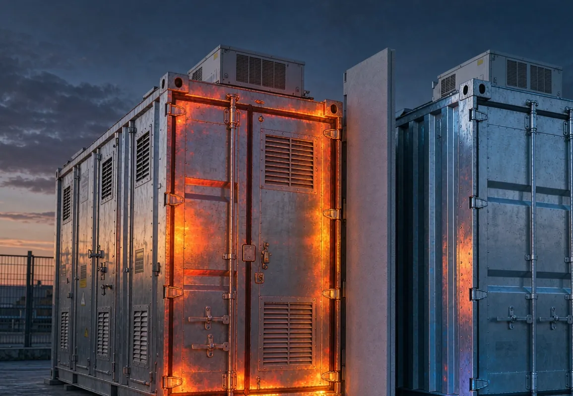
Working environment and compliance. National energy-conservation guidance puts explicit caps on furnace outer-wall temperature. Japan's Energy Conservation Law sets, at a 20 °C ambient, limits of 140 °C (roof) / 120 °C (side) for a 1300 °C furnace, 125 / 110 at 1100 °C, and 110 / 95 at 900 °C. India's BEE guidelines table a design limit of 120 / 100 / 120 °C (roof / side / bottom) for furnaces above 1000 °C, with a tighter target of 110 / 85 / 100 °C.
So the design question is not "how much fuel?" but "what shell temperature do I want, and what thickness of backup insulation gets me there within the wall space I have?"
The physics in one line
Heat through a composite wall is one-dimensional steady conduction:
`Q = A · (T_hot − T_ambient) / (L₁/k₁ + L₂/k₂ + 1/h_o)`
where `L₁/k₁` is the thermal resistance of the working refractory, `L₂/k₂` is the resistance of the backup layer, and `h_o` is the outside film coefficient (about 10–15 W/m²K for natural convection plus radiation). The shell temperature is whatever the outer surface settles at once that heat flux reaches the casing.
The trick with a microporous board is the `k₂` term. At the temperatures a backup layer actually sees — the cold face of the working lining, typically 600–900 °C — microporous board holds a conductivity that ceramic fibre and calcium silicate only reach at a fraction of the thickness.
Conductivity at service temperature, not at 25 °C
This is the figure that decides the wall. From manufacturer datasheets:
| Mean temp | Microporous board (Promat MICROTHERM 1000R) | Microporous board (Morgan WDS Ultra) | Ceramic fibre board | Calcium silicate | |---|---|---|---|---| | 200 °C | 0.023 | 0.022 | ~0.05 | ~0.06 | | 400 °C | 0.026 | 0.027 | ~0.09 | ~0.09 | | 600 °C | 0.031 | 0.034 | ~0.14 | ~0.12 | | 800 °C | 0.039 | 0.044 | ~0.19 | ~0.16 |
Sources: Promat MICROTHERM PANEL-1000R and Morgan WDS Ultra Board datasheets. Ceramic-fibre and calcium-silicate columns are rounded from the same comparative datasheets; ceramic-fibre conductivity at 800 °C is roughly five times the microporous value, not 1.2 times.
The two SLM grades follow the same curve. SLM-1000 is specified at λ ≤ 0.024 W/mK at 600 °C with permanent linear change ≤ 2.0 percent after 24 h at 1000 °C; SLM-1200 at λ ≤ 0.028 W/mK at 800 °C with permanent linear change ≤ 1.5 percent after 24 h at 1200 °C. The SLM-1000 vs SLM-1200 comparison guide gives the full temperature/property split for picking the grade against your working-lining cold-face temperature. For most reheating-furnace backups the cold face sits under 900 °C, so SLM-1000 is the usual choice; for the hotter zones and for heat-treatment furnaces running near the top of the band, SLM-1200 earns its rating.
Thickness equivalence is the headline
The reason microporous board is worth the price in a furnace wall is thickness. Published equivalency figures:
mm of microporous board ≈ 150 mm of ceramic-fibre blanket (Bloor Engineering).
mm of microporous board ≈ 40 mm of calcium silicate ≈ 50 mm of ceramic-fibre board (Topower).
mm of MICROTHERM at a 900 °C internal temperature gives the same shell temperature as 360 mm of high-temperature fibre (Promat).
In a furnace where the wall cavity is already thin and you cannot thicken it without losing hearth space, that 6-to-1 ratio is the whole argument. You get the shell temperature you want in the thickness you have.
Three measured retrofits
Numbers from published engineering cases, not vendor claims sheets:
Ethylene cracking furnace, 1150 °C internal. Adding 30 mm of nano-microporous backup dropped the shell from 95–110 °C to 65–70 °C, meeting the below-70 °C requirement, with a reported 300,000 RMB/year saving (Tianjin Petrochemical, via Gutejn).
Steel reheating furnace, originally aluminium-silicate fibre, wall above 120 °C. Switching the backup to microporous board brought the wall below 60 °C, cut heat loss by more than 30 percent, saved about 12 percent on gas, and paid back in 2.5 years (Zhengzhou Jinshan Refractory case).
Walking-beam reheating furnace, ArcelorMittal Bremen. Replacing RCF modules with a microporous castable (Almatis FLB-11/150-I1) cut overall energy use 35 percent and skid heat loss more than 60 percent, with payback under one year (Almatis technical paper).
Note the spread. Case 2 reports 12 percent gas saving and 2.5-year payback; case 3 reports 35 percent and under one year. The difference is scope: case 3 changed the skid lining too. Treat 1.5–4 percent wall-only fuel recovery as the conservative expectation, and anything higher as a sign the retrofit touched more than the wall.
Continuous versus batch: where the board helps most
A continuous reheating furnace runs at steady state, so the wall loss is pure conduction and the benefit is the steady shell-temperature and fuel saving above. A batch, bogie or pit furnace cycles, and most of its heat leaves not through the wall but into the lining itself as stored heat, then out during cooling. That is where low heat storage matters.
Published storage figures: ceramic-fibre lining stores only 5–10 percent of the heat of dense refractory brick; microporous board stores 3–5 percent. One cited retrofit from dense castable to ceramic-fibre modules cut wall heat storage 80 percent and wall loss 45–60 percent. A quantitative "microporous alone shortens heat-up by X percent" figure for intermittent furnaces was not found in a published source — the available numbers are for ceramic fibre, not microporous — so we will not put one in. The qualitative point holds: in a cycling furnace, the board's low density and low heat capacity reduce the energy parked in the lining each cycle, which is a larger lever than the steady-state wall loss alone.
Sizing the backup layer, step by step
Fix the target shell temperature. Take it from your energy-conservation limit (e.g. 100 °C side wall at >1000 °C internal, per BEE) or your safety limit (60 °C for manned aisles), then subtract ambient to get the allowable temperature drop across the wall.
Get the working-lining resistance. Measure or take from the refractory spec its thickness `L₁` and conductivity `k₁` at its operating mean temperature. `R₁ = L₁/k₁`.
Compute the resistance the backup must supply. `R₂ = (T_hot − T_ambient) / Q_target − R₁ − 1/h_o`, where `Q_target` is your allowed heat flux. If you prefer to work from shell temperature directly, solve `T_shell = T_ambient + Q · (1/h_o)`.
Convert to thickness with the board's conductivity at its own mean temperature. `L₂ = R₂ · k₂(T_mean)`. Use `k₂` at the backup layer's mean temperature (cold face of working lining to shell), not at 25 °C — at 800 °C the Promat 1000R board is 0.039, not 0.023.
Check the space. If `L₂` exceeds the cavity, either accept a higher shell temperature or move to the higher-grade board; the datasheet guide shows how to read a conductivity curve so you are sizing from the right temperature point.
Worked example: hot face 1200 °C, ambient 30 °C, working lining 200 mm of castable at k = 0.8 (R₁ = 0.25), target shell 100 °C. Allowable flux `Q = (1200 − 30) / (0.25 + 1/12) ≈ 3900 W/m²`. Shell drop across film = 3900 / 12 ≈ 325 °C — already over, so the working lining alone cannot hold 100 °C; backup required. Solving for `R₂` gives about 0.11 m²K/W. At 800 °C the board's k ≈ 0.039, so `L₂ ≈ 4.3 mm` — unrealistically thin, which tells you the real constraint is the working lining, not the board. The board's value appears when the cavity is tight and you need a low shell without thickening the whole wall.
The mistakes that ruin the specification
Comparing at 25 °C. Datasheets lead with the room-temperature number. At 800 °C the gap between microporous and ceramic fibre is roughly fivefold; at 25 °C it looks like 1.2-fold. Size from the operating-temperature conductivity or you will under-specify.
Ignoring joints and thermal bridges. A butt joint wider than a few millimetres opens a convection channel where local loss can double. Stagger the joints (brick-bond, not stacked), and seal cut edges with aluminium-foil tape. The joint problem covers joint detailing for exactly this.
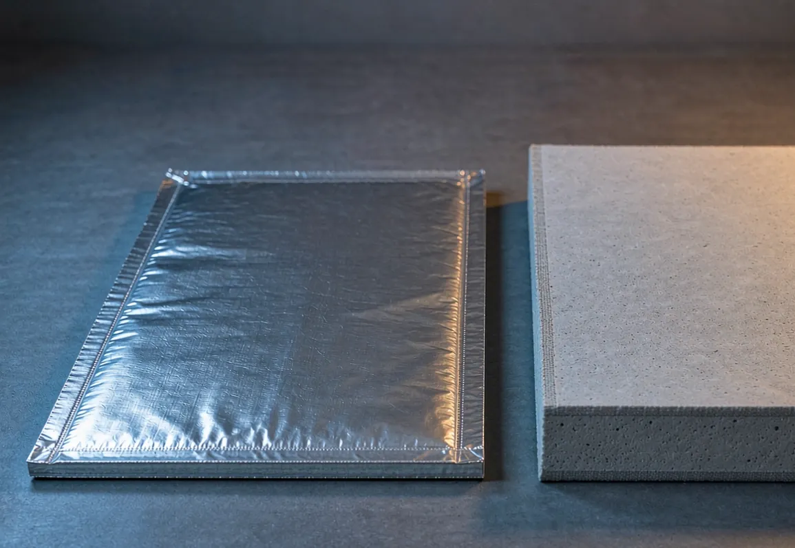
Letting the board get wet. A wetted microporous board's conductivity climbs above 0.08 W/mK and it cannot be dried back to spec — the moisture is trapped in the evacuated pores. Keep it foil- or PE-encapsulated during storage and installation. The storage and cutting guide covers handling and encapsulation.
Over-compressing. More than about 5 percent compression damages the microporous structure. Support the board, do not crush it against the casing.
Treating wall-only as the whole answer. The wall is 4–8 percent. If your furnace's real problem is flue-gas or skid loss, insulation helps the shell but will not fix the energy bill. Scope honestly and pair the lining work with combustion and recovery upgrades where they pay.
How to verify the result
After installation, confirm the shell temperature with a calibrated infrared survey at full operating temperature, and compare against the target from step 1. A performance verification write-up of before/after shell temperature and fuel draw is the evidence your energy manager and your auditor want. Before you buy, a supplier audit checklist keeps the board's stated conductivity and permanent-linear-change numbers from being tested for the first time on your furnace.
FAQ
Will microporous board replace my working refractory? No. It is a backup layer on the cold face of the refractory. The refractory takes the erosion and the temperature; the board takes the heat flux.
Is it worth it if wall loss is only 4–8 percent? For fuel alone, marginally. For shell temperature, casing life, safety and compliance, yes — and in thin-wall or cycling furnaces the low heat storage adds a second benefit the steady-state number misses.
Which grade, 1000 or 1200? Match the board's rating to the cold-face temperature of your working lining. Under 900 °C cold face, SLM-1000. At or above it, SLM-1200.
How fast does it pay back? Published wall-only cases run 1 to 2.5 years; broader retrofits that also address skids come in under a year. We were unable to locate a published "months" figure specific to microporous board in steel reheating furnaces, so quote a range, not a point.
Does it help a batch furnace more or less than a continuous one? Differently, not more or less: continuous furnaces gain steady shell-temperature and fuel saving; batch furnaces gain low heat-storage per cycle. Both benefit.
What we need to quote
Send the furnace type (reheating, annealing, normalizing, tempering, bogie, pit), internal operating temperature, the working-lining material and thickness you are keeping, the available backup-cavity depth, and your target shell temperature or energy-conservation limit. The RFQ template lists exactly what to send so the quote comes back sized, not guessed.
The anchored ladle back-up assembly is the same board doing the same job behind refractory in a different shape — the furnace wall is where most plants leave the largest unrecovered slice of their fuel bill, and the smallest, safest fix.