Oct 6, 2026
UL 9540A Edition 6 Made Passive Barriers Mandatory: What a BESS Enclosure Wall Has to Survive
Edition 6 of UL 9540A makes large-scale fire testing the deciding level and requires passive containment with active systems disabled, so thermal barriers, fire-resistant materials and internal segmen
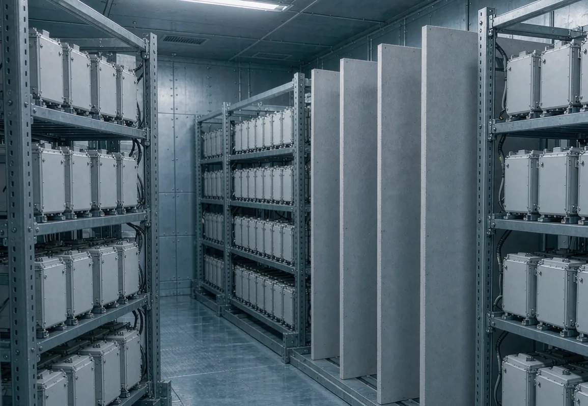
The sixth edition of ANSI/CAN/UL 9540A turns large-scale fire testing from an optional extra into the main event, and it quietly changes what a battery enclosure wall is for. If your propagation strategy currently depends on the HVAC or the suppression system doing its job, the new edition asks what happens when they are switched off. That question has a material answer, not a controls answer.
This article is for anyone specifying the barrier inside or between BESS enclosures. It collects the acceptance numbers that are publicly reported for Edition 6, the measured fire conditions those numbers come from, and what the candidate barrier materials actually do at temperature. Where a figure comes from a third-party reading of the standard rather than the standard text itself, that is flagged — verify against the published document before you commit to a test plan.
What changed, and why it reaches the wall
Four shifts matter for enclosure design.
Large-scale fire testing (LSFT) is now a required part of the installation-level evaluation for most non-residential systems. Previously it sat alongside the cell, module and unit levels as something you could commission for extra confidence. Under Edition 6 it is the level that decides compliance.
Annex C, covering large-scale deflagration testing, moved from an informative annex to a normative one. UL's own guidance ties it to enclosures that do not have deflagration venting designed to NFPA 68: if your enclosure geometry and gas composition present an explosion risk, that behaviour has to be measured, not argued.
Vertical propagation is now explicitly tested. SGS's reading of the sixth edition states that thermal runaway must be initiated across at least one full vertical module grouping, which is the configuration that produces the chimney effect — heat and flame accelerating up a rack rather than spreading sideways.
And the unit level has been de-emphasised. UL states that Edition 6 no longer requires unit-level testing for non-residential BESS. The centre of gravity moved from "does this cabinet behave" to "does this installation behave", and installations are made of barriers and spacing.
The application map sorts insulation duties by temperature band; BESS fire barriers sit in an unusual corner of it, because the requirement is not steady-state efficiency but survival for a defined number of hours.
The acceptance numbers being reported
These are the figures circulating in technical summaries of Edition 6, including SGS SafeGuardS 068/26 and the ULSE task group proposal behind Section 10. Treat them as the basis for design conversations, not as a substitute for buying the standard.
Target enclosure cells — reported limit of 90% of cell vent temperature (Tvent)
Module enclosures in the target unit — Tvent
Inner wall of the target enclosure — Tvent
Reference wall — temperature rise of 97 K (the 97 °C / 175 °F figure appears verbatim in earlier Section 10.5.1 instrumented-wall text that FSRI reproduced)
Structural steel inside a building — 538 °C surface temperature
Debris — contained within 1.5 m
After suppression stops — no re-ignition for 24 hours
Heat flux — 12.5 kW/m² is the limit proposed for the instrumented wall, with its technical basis drawn from NFPA 80A
Third-party readings of the published edition additionally describe a termination condition below 100 °C held for three hours, and a graded set of limits using Tvent and 110% of Tvent depending on measurement location. Those specific splits are the ones most worth confirming against the text itself, because they determine where your thermocouples go and what margin you need.
Two structural points survive regardless of which numbers end up in the final clauses. The test arrangement has to reflect the real installation, including module layout and minimum spacing. And the reference wall, the steel, the debris field and the re-ignition window are all judged on passive behaviour.
Passive-first, in the words that matter
SGS states it plainly: during installation level testing, active propagation-prevention systems must be disabled within the enclosure of origin. The sixth edition introduces a passive-first philosophy for outdoor ground-mounted systems, requiring thermal runaway containment without reliance on HVAC or suppression. UL's proposal frames the scenario as the condition after single-use, non-continuous protection systems are exhausted, and requires the doors or openings of the origin enclosure to be open, with the choice driven by the deflagration assessment.
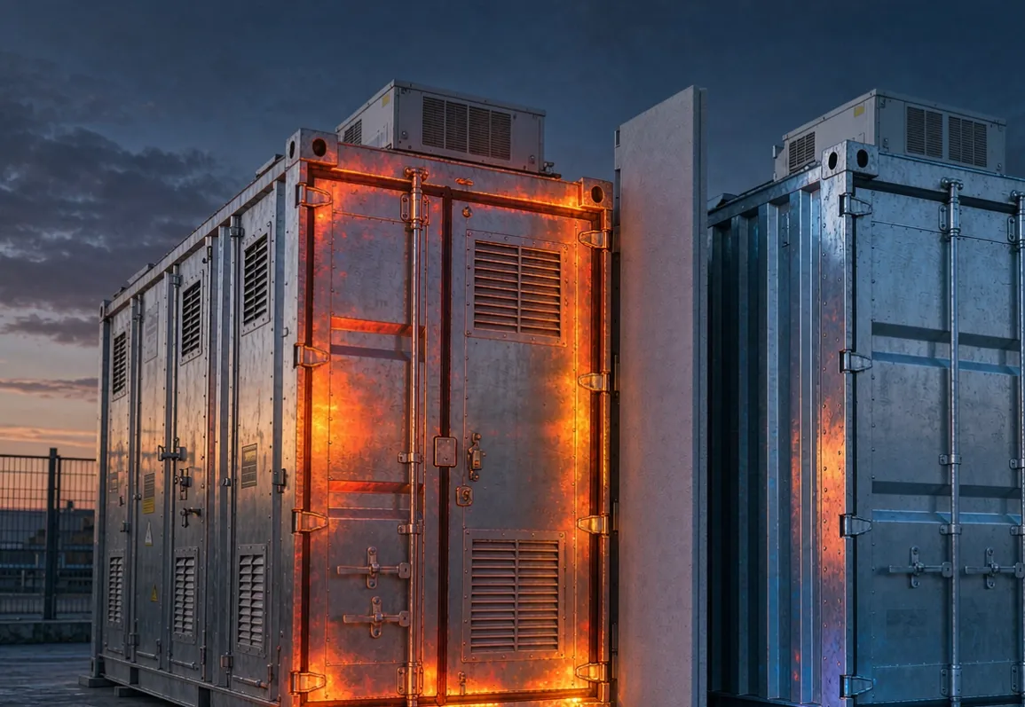
The procurement consequence is direct. Thermal barriers, fire-resistant materials and internal segmentation are no longer one layer of a defence that also includes fans and nozzles. During the test they are the whole defence, and a design that leans on active cooling alone is a design that risks non-compliance.
For material selection this flips the usual question. It is not "what does the barrier contribute alongside the suppression system" but "what does the barrier hold on its own for thirteen hours".
What the fire actually is
Numbers first, because most barrier specifications fail here rather than at the material stage.
Full-enclosure burn tests published by manufacturers and reported in industry coverage reached peak temperatures of 1296 °C (Jinko) and 1297 °C (Envision), with burn durations of 13 hours 40 minutes and more than 49 hours respectively.
At cell level, published measurements put vent gas temperature above 1370 °C for 21700 NMC811 cylindrical cells and above 1150 °C for large tabless cylindrical formats, with 750 °C measured at a double-sided vent and 450 °C at a side rupture. Cell surface peaks run 300 °C for ordinary venting, around 500 °C for double-sided venting and up to 900 °C on side rupture; 18650 NCA cells at full state of charge reached 710 °C while LFP reached 354 °C.
Propagation pace is slower than intuition suggests. A unit-level UL 9540A hazard mitigation analysis recorded 15 to 20 minutes per cell spreading through a module, with propagation stopping after three cells. Another reported module-level result describes roughly one hour to a single adjacent cell.
Compare that with the cell-to-cell world the battery-pack barrier article covers, where the governing thresholds are minutes: GB 38031 and ECE R100 work to a five-minute no-propagation requirement, and Aspen reports a 2.35 mm PyroThin layer at 50% compression holding an adjacent 62 Ah prismatic cell to a 130 °C peak at five minutes with no runaway at 30 minutes.
A cell-level barrier and an enclosure-level barrier are solving different problems. One is a transient event measured in minutes, where a thin layer with some heat capacity can win. The other is a sustained 1296 °C source that keeps injecting heat for longer than any shift, where steady-state conduction governs and the question is what temperature the far side sits at for hours.
Candidate materials at real temperatures
The trap in this table is the headline conductivity. Every material is quoted at 25 °C or 200 °C, and the fire is not.
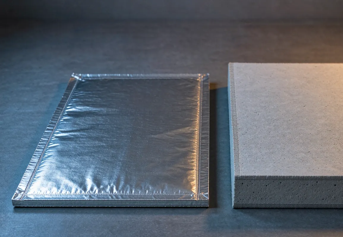
Microporous nano board, 1000 °C grade — 3–50 mm, 240 kg/m³, 0.023 W/mK at 200 °C, 0.031 at 600 °C, 0.039 at 800 °C, shrinkage under 3% at 1000 °C
Microporous nano board, 1200 °C grade — 3–40 mm, 400 kg/m³, 0.029 / 0.039 / 0.044 W/mK at the same temperatures
Aerogel blanket — 3–10 mm, 150–200 kg/m³, 0.018 W/mK at 25 °C rising to 0.068 at 600 °C, 650 °C service limit
Specialty aerogel thermal barrier (PyroThin class) — 0.5–3 mm, rated to 1400 °C; published comparisons put mica at 1000 °C, metals at 1150 °C, intumescent plastics at 430 °C and silicone foam at 150 °C
Phlogopite mica sheet — 0.5–3 mm, 1.8–2.45 g/cm³, conductivity reported at 0.3–0.4 W/mK depending on direction, 700 °C continuous and 1000 °C intermittent
Ceramic fibre board — 5–150 mm, 240 kg/m³, 0.11 W/mK at 600 °C, classified 1260 °C with practical use around 1050 °C
Calcium silicate — around 230 kg/m³, 0.050–0.065 W/mK, 1000 °C
Mineral wool — cheapest by a wide margin, and the first to lose mechanical coherence in this temperature range
Read the aerogel line against the microporous line and the design-relevant difference appears. Aerogel starts lower at room temperature, 0.018 against 0.023, and is nearly four times worse by 600 °C at 0.068, against 0.039 for the microporous board. In a fire that runs past 1000 °C for hours, the room-temperature figure is close to irrelevant, and a material selected on it will be thinner than the duty requires.
Cost reporting from suppliers and industry summaries puts microporous board in the 80–150 €/m² range, aerogel blanket at 120–220 €/m², ceramic fibre at 18–35 and mineral wool at 10–22. Treat those as indicative ranges rather than quotations; the aerogel-to-microporous ratio of roughly 1.3 to 1.5 is the part that stays consistent across sources.
The datasheet guide covers which property lines carry real information. For this duty the useful ones are the conductivity curve across temperature, the permanent linear change after heating, and whether the board keeps structural integrity in the encapsulation you intend to use.
Sizing the barrier: start from duration
Steady-state conduction is the wrong model for a five-minute cell-level test and a reasonable one for a thirteen-hour enclosure fire. That difference is the whole sizing argument.
For a sustained source, thickness follows from the temperature you need on the cold face and the conductivity at the temperature the material will actually sit at, not the conductivity on the datasheet's first line. Work the thickness sizing method backwards: fix the allowable cold-face temperature from the acceptance limit you are designing against, take λ at the mean temperature of the layer, and solve.
Two corrections then apply. The first is that the mean temperature is high, so the λ you use is the 600–800 °C value, which for aerogel is triple the headline number. The second is that thermal bridges dominate the result once the board is doing its job. Cable penetrations, bolted standoffs, rack steel and door frames carry heat past the barrier in a way no thickness calculation captures, and on an infrared survey they read as discrete hot spots rather than uniform warmth.
Where enclosure barriers fail in practice
Penetrations and joints. A barrier with unsealed cable ways is a barrier with holes. Layout, cutting tolerance and joint treatment matter more here than in furnace work because the enclosure is full of services.
Fixings that let go. Steel supports and brackets lose strength well below the temperatures the board survives. Barrier held by hardware that softens at 500 °C ends up on the floor.
Material selected on room-temperature λ. Covered above, and the most common sourcing error in this application.
Wrong face. The barrier belongs on the side away from the flame, protected by whatever facing the design uses. It is not a flame-facing material.
Dust and fibre classification. Refractory ceramic fibre carries a carcinogen classification under EU REACH; encapsulated microporous board is supplied as a cut-to-size panel without respirable fibre. That affects installer PPE, site waste handling and, increasingly, the customer's own ESG review.
What to ask for in the barrier RFQ
Ask for the conductivity at four temperatures rather than one, the permanent linear change at your maximum exposure, the density and cold crushing strength, the encapsulation method and what it is rated to, the cutting tolerance you can hold on site, and the fibre classification documentation. Ask what the material does after two hours at temperature, not what it does at delivery.
The RFQ template has the field list. For this application, add one line that is unusual elsewhere: state the acceptance limit and the burn duration you are designing against, and ask the supplier to confirm thickness against those rather than against a standard product thickness.
On receiving it, the checks are dimensional, density and a conductivity spot check — the incoming inspection logic in the storage and cutting guide applies directly, and the performance verification method is how you confirm the installed layer did what the calculation said.
Questions that come up
Is aerogel or microporous board the right default? For a sustained high-temperature enclosure duty, microporous board holds its conductivity better above 600 °C and is rated to 1000 or 1200 °C, while blanket aerogel is commonly limited to 650 °C. Specialty aerogel barriers rated to 1400 °C exist, at a cost premium, and are competitive where thickness is severely constrained. The SLM-1000 vs SLM-1200 comparison guide explains how the two microporous grades differ.
Do we still need unit-level testing? UL states Edition 6 no longer requires it for non-residential systems. Installation-level testing is where the compliance weight sits now, which is why enclosure barrier design moved from a detail to a deciding factor.
Can we reuse the cell-level barrier thickness at enclosure level? No. The five-minute and thirty-minute cell-level results are transient and achieved at millimetre thicknesses. The enclosure duty is a 1296 °C source for hours, and thickness has to come from a steady-state calculation against the acceptance temperature.
What about spacing instead of barriers? NFPA 855 settings reported for the 2026 revision keep a 3 ft (0.91 m) minimum separation for lithium-ion groups above 50 kWh per group, with a 50 kWh cap per single cabinet and the 600 kWh threshold logic removed. Spacing can only be reduced on the basis of UL 9540A and LSFT data. Barriers and spacing are alternatives only in the sense that one buys you relief from the other, and the relief has to be evidenced.
---
SLM supplies high-strength nano insulation boards for BESS enclosure walls, internal segmentation and inter-unit barriers, in 1000 °C and 1200 °C grades. For a barrier specification, send the acceptance temperature you are designing against, the burn duration in your test plan, the available wall build-up thickness and the penetration layout. See the anchored ladle back-up assembly for typical stack arrangements, or reach us at sales@slmthermal.com.