Oct 27, 2026
NFPA 855 Separation Distances: How to Get From 10 ft to 3 ft, and Why a 2-Hour Fire Wall Is Not the Same Test
There is no kilowatt-hour lookup table in NFPA 855. Separation is fixed - 3 ft between units indoors, 10 ft from an outdoor installation to any exposure - and the standard then gives you a short list
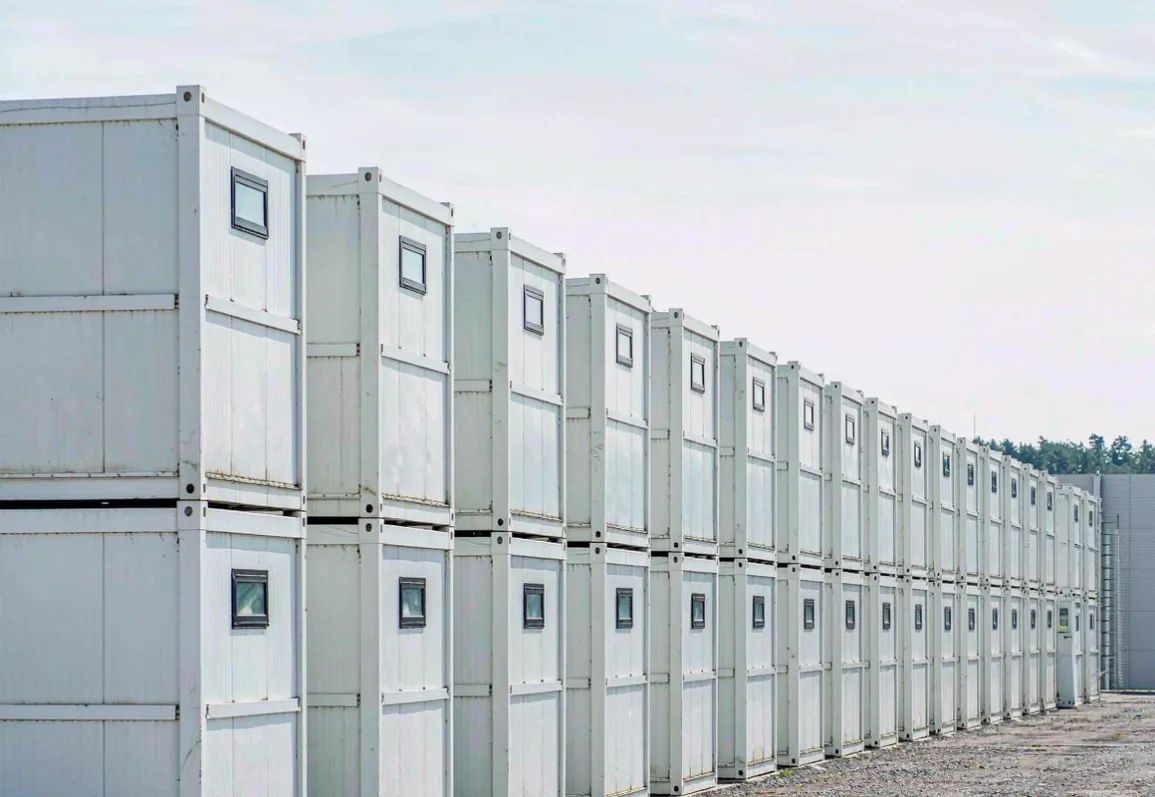
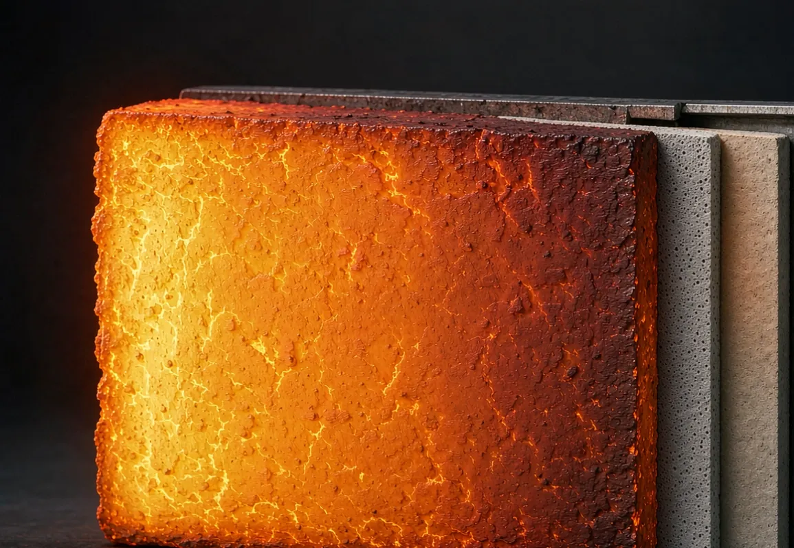
Ask ten people on a BESS project what separation distance NFPA 855 requires and most of them will describe a table that does not exist. There is no kilowatt-hour lookup. The standard sets fixed distances — 3 ft between units and groups indoors, 10 ft from an outdoor installation to anything that can burn or anyone who needs to get away — and then offers a short list of ways to cut the outdoor number down to 3 ft. Every one of those reductions is bought with something: a fire barrier, a rated enclosure, or a large-scale fire test. That is the whole commercial logic of passive protection on a storage site. Land is a line item, distance is what consumes it, and the barrier is what buys it back. The same trade shows up wherever a hot face has a cold side, which is what the /posts/nano-insulation-board-application-map collects across other industries.
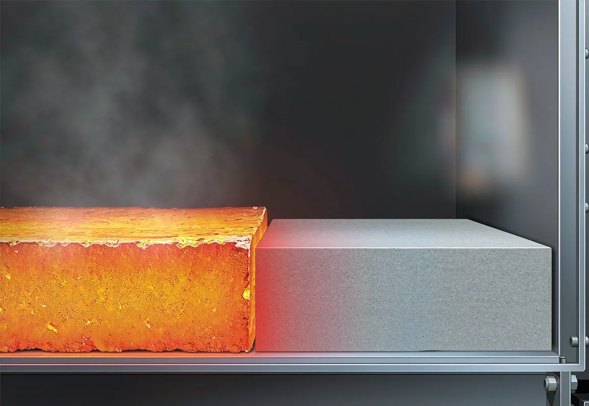
The complication, and the reason this article exists, is that the two tests people treat as interchangeable are not. A 2-hour fire wall rated to ASTM E119 is allowed to run its unexposed face to roughly 200 °C and still pass. The cell sitting on the other side of that wall goes into thermal runaway at trigger temperatures that published UL 9540A reports put between 179 °C and 358 °C. A wall can be fully code-compliant and still sit inside the band where the neighbouring cell lights.
What the standard actually requires
The current edition of NFPA 855, Standard for the Installation of Stationary Energy Storage Systems, is the 2026 edition, but most jurisdictions still enforce the 2023 or 2020 text. Clause numbers below are given for both where they differ, because an AHJ will cite the edition it has adopted.
| Requirement | Default value | Clause (2020 / 2023) | |---|---|---| | Between ESS units, and between a unit and a wall, indoors | 3 ft (914 mm) | 4.6.3 / 9.4.2.2 | | Maximum energy per group indoors | 50 kWh | 4.6.2 / 9.4.2.1 | | Outdoor installation to property line, road, building, combustibles, hazmat, high-piled storage | 10 ft (3048 mm) | 4.4.3.3 / 9.5.2.6.1 | | Outdoor installation to vegetation and to means of egress | 10 ft | 4.4.3.6.1 / 4.4.3.4.1 | | Exhaust outlet to doors, windows, HVAC intakes | 15 ft | 4.4.3.3.6 | | Wall-mounted single units of 20 kWh or less: between units / to openings | 3 ft / 5 ft | 4.4.3.10 |
Two things are worth pulling out of that table. First, there is no distance that scales with capacity — a 5 MWh container and a 500 kWh cabinet are treated the same way for separation. What scales with capacity is the stored energy ceiling per fire area, which is a separate control entirely. Second, the distances are not negotiated per project. They are fixed until you invoke one of the reduction paths, and every reduction path is documented in the standard rather than left to opinion.
The capacity ceilings sitting behind the distances
Distance is only one of two controls. The other is how much energy you may put in one fire area before the fire area has to be subdivided.
| Battery chemistry | Maximum stored energy per fire area | Source | |---|---|---| | Lithium-ion | 600 kWh | NFPA 855-2023 Table 9.4.1 / IFC Table 1207.5 | | Flow, sodium-nickel-chloride | 600 kWh | same table | | Lead-acid, Ni-Cd, Ni-MH, Ni-Zn, Zn-MnO₂ | Unlimited | same table | | Other electrochemical, capacitors | 20 kWh | same table | | Dedicated-use building | No limit stated | IFC Table 1207.7 | | Remote outdoor installation, beyond 100 ft | Not applicable | IFC Table 1207.8 |
Those ceilings are raised the same way distances are reduced: an AHJ approval backed by a hazard mitigation analysis and large-scale fire test data. In practice this is why the 600 kWh figure matters so much to a containerised project. A single 5 MWh enclosure is not a permitted unit in a mixed-occupancy fire area; it is permitted because it is a listed system with its own test record and its own outdoor siting.
The outdoor unit also has a physical size limit. A walk-in outdoor enclosure is capped at roughly 53 ft × 8.5 ft × 9.5 ft (16.2 × 2.6 × 2.9 m); anything larger is treated as an indoor installation and inherits the indoor rules (NFPA 855-2020 §4.4.3.2.1–2.2).
Three documented ways to get from 10 ft to 3 ft
This is the part that pays for barriers.
1. A 1-hour freestanding outdoor fire barrier. The 2020 text is explicit: the required separation "shall be permitted to be reduced to 3 ft (914 mm) when a 1-hour freestanding fire barrier, suitable for exterior use, and extending 5 ft (1.5 m) above and 5 ft (1.5 m) beyond the physical boundary of the ESS installation is provided to protect the exposure" (§4.4.3.3.1). Note the geometry. It is not a wall between two containers; it is a free-standing screen on the exposure side, and it has to be tall enough and wide enough to shadow the whole installation.
2. A 2-hour non-combustible exterior wall with no openings. Where the exposure is a building, a 2-hour rated wall with no openings takes the separation to 3 ft.
3. A 2-hour rated enclosure. "…reduced to 3 ft (914 mm) where the enclosure of the ESS has a 2-hour fire resistance rating established in accordance with ASTM E119 or UL 263" (§4.4.3.3.5). This is the path most container vendors pursue, because the rating is a property of the product they ship rather than a site-built structure.
4. Large-scale fire testing. Where the installation-level test under UL 9540A demonstrates that a fire in one unit does not propagate to its neighbour, the AHJ may approve reduced separation. NFPA 855-2020 §4.1.5.2 requires the test to show exactly that, and §4.1.5.3 adds that for indoor installations the fire must be contained within the room for the full fire-resistance duration of the separating construction — two hours, if the separation is a two-hour barrier. The 2026 edition formalises this in Annex G.11, with acceptance framed as: no module surface temperature in the adjacent unit exceeding cell vent temperature, no ignition of combustibles in the adjacent enclosure, and no venting or thermal runaway in the adjacent unit.
Path 4 has no fixed lower limit in the standard. The number is whatever the AHJ accepts, which is why the test report matters more than the distance claim — a point covered in detail in the UL 9540A report guide.
Why a 2-hour wall and a thermal-runaway barrier are different tests
Here is the gap that catches projects out.
ASTM E119 and UL 263 fire-resistance tests have two acceptance legs: the assembly must stay in place, and it must limit heat transmission. The heat-transmission leg allows an average temperature rise on the unexposed face of 139 °C and a single-point rise of 181 °C above ambient (FEMA 403, Appendix A). EN 1363-1 uses 140 K average and 180 K maximum. A wall that finishes a two-hour test at 180 °C above ambient on its cold face has passed.
Now put a lithium cell on the other side. Published UL 9540A cell-level data for commercial cells gives:
| Cell | Vent temperature Tvent | Thermal runaway trigger Ttr | Source | |---|---|---|---| | REPT 280 Ah | 258.4 °C | 357.9 °C | third-party UL 9540A report | | Hithium 280 Ah | 274.3 °C | 330.4 °C | third-party UL 9540A report | | CATL 157 Ah LFP | 174 °C | 239 °C | third-party UL 9540A report | | LFP 314 Ah | 127.9 °C | 179.8 °C | FSRI installation demonstration report | | 18650 format | 130 °C | 204 °C | third-party UL 9540A report |
The lowest trigger temperature in that set is 179.8 °C. The E119 cold-face pass limit is 181 °C at a single point. Those two numbers are not comfortably apart; they are the same number to within measurement noise. And the heat source is not a slow cellulose curve. UL 9540A unit-level testing recorded enclosure surface temperatures up to 670 °C, module-level peak heat release rates near 3935 kW, and jet temperatures at a vent of roughly 1150 °C.
So the honest statement is this: a fire-resistance rating and a thermal-runaway barrier are answering different questions. The rating asks whether the wall survives a building fire and slows heat transmission to a threshold written for occupant safety. The barrier asks whether the cell on the other side stays below its trigger temperature while a vent jet plays on the wall for minutes. Passing the first does not demonstrate the second. We could not locate an official UL or FSRI statement saying this in those words; the conclusion follows from putting the two published acceptance criteria side by side, and you should confirm it with your AHJ rather than assume it.
Where the barrier question is treated directly, see the enclosure wall analysis and the battery-pack barrier treatment at cell level.
What the barrier has to hold, in numbers
Because the acceptance criterion is a temperature at a neighbouring cell rather than a flame-through time, the useful data is thickness-to-back-face-temperature, measured at real fire temperatures.
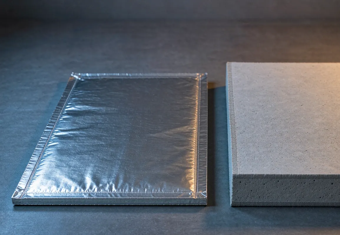
| Barrier | Thickness | Exposure | Cold face / adjacent cell result | Source | |---|---|---|---|---| | Wacker silicone-glass laminate | 2 mm | 1150 °C vent jet, 9–11 mm standoff, nine 35 Ah NMC cells | back face below 140 °C, no burn-through | manufacturer test report | | Silica aerogel mat | 2 mm | 35 Ah cell triggered, 874 s | adjacent cell 175.4 °C and 109.4 °C versus 441.3 °C unprotected; safety valve did not open | manufacturer data | | PI aerogel | 2 mm | prismatic cell propagation | propagation interval extended from 10 s to 595 s | peer-reviewed study | | SiO₂ aerogel blanket, λ = 0.021 | 2 mm | module propagation | roughly 50 percent heat transfer reduction, propagation blocked | Applied Thermal Engineering | | Microtherm-based board system | 34 mm | EN fire resistance | EI120 | Promat passive fire protection range | | Microtherm-based board system | 27 mm | in-enclosure cell separation | up to 20 percent more cell capacity in the same envelope | Promat |
Two observations matter for specification. The first is that 2 mm is enough at cell level and nowhere near enough at enclosure level — the heat source changes by an order of magnitude between a single venting cell and a container that has gone to 670 °C on its shell. The second is the one with commercial weight: Promat publishes a 27 mm microporous-based separation that returns roughly 20 percent more cell capacity inside the same enclosure envelope. That is the same argument as distance reduction, applied inside the box. You are not buying insulation; you are buying back volume that was being spent on clearance.
A useful screening rule from the propagation literature: complete suppression in a 314 Ah LFP module required a thickness-to-conductivity ratio d/λ of at least 35 mm·m·K/W, with λ ≤ 0.035 W/mK as the critical conductivity, and d/λ ≥ 12 needed for at least 150 s of delay. Treat it as screening only — the underlying paper could not be located by DOI, so it is a secondary citation.
What the distance is worth
Separation distance is not a safety abstraction on a utility-scale site; it is land.
Containerised plant occupies roughly 1000 ft² per MWh of enclosure footprint, with site-level densities of about 20 to 40 MWh per acre once setbacks are included (industry sizing reference, secondary source).
Land is reported at 15 to 20 percent of total CAPEX for projects above 100 MWh in Europe (vendor article — treat as indicative, not authoritative).
Reducing outdoor separation from 10 ft to 3 ft removes 7 ft per exposure side. On a long row of containers with setbacks on multiple sides, that is the difference between a site that fits the parcel and one that needs the next one.
The arithmetic is site-specific and we have not found a published case pairing barrier thickness with a measured MWh-per-acre gain, so do not let anyone quote you a percentage. What is defensible is the direction: every foot of separation you can legitimately remove is land you do not buy, and the two documented routes to remove it are a rated barrier or a test record.
How to specify a barrier for this duty
Establish which test you are answering. If the AHJ wants separation reduction, they want either a fire-resistance rating (E119 / UL 263) or an installation-level UL 9540A result. Ask which, in writing, before you buy material.
Get the real thermal boundary condition. Not "fire". The numbers you need are the vent jet temperature and duration, the expected shell temperature, and the trigger temperature of the specific cell in the adjacent unit. Published Ttr values span 180 to 358 °C; a generic specification will miss both ends.
Size on conductivity at temperature, not at 25 °C. Published conductivity curves for barrier materials diverge sharply above 400 °C. A board that reads 0.023 W/mK at room temperature and 0.030 to 0.044 at 800 °C behaves very differently from a blanket that goes from 0.086 to 0.19 over the same range. Our datasheet guide covers how to read those curves, and the thickness sizing method walks the calculation.
Decide whether the barrier is structural. A separation screen that has to stand 5 ft above and 5 ft beyond the installation is a structure with a thermal layer on it, not a thermal layer alone. Microporous board in this class runs 0.15 to 0.67 MPa compressive strength — it does not carry load, and it goes behind a protective facing.
Detail the joints before you detail the boards. On a long screen the joint length dominates. Unsealed gaps are where the joint problem erases the rating you paid for.
Confirm the grade for the temperature. Where the calculated interface temperature exceeds roughly 1000 °C, the SLM-1000 vs SLM-1200 comparison guide sets out which of our high-strength nano insulation boards is the correct grade.
Common mistakes
Looking for a kWh-based distance table. It does not exist in NFPA 855. The capacity-dependent control is the stored-energy ceiling per fire area, which is a different mechanism.
Citing the 20 ft and 3-hour wall rule. That rule is in Chapter 14, which covers storage of batteries, not installation of ESS. Applying it to a BESS layout produces a design that is simultaneously over-conservative and wrong.
Assuming a 2-hour rating proves propagation control. It proves a fire-resistance rating. The numbers above show the cold-face pass limit and the lowest published cell trigger temperature are effectively the same value.
Buying an indoor barrier for outdoor duty. The reduction path specifies "suitable for exterior use". Moisture irreversibly damages microporous structure in standard grades.
Treating the 5 ft above and 5 ft beyond requirement as optional. It is in the clause text. A screen sized to the container footprint does not qualify.
Evaluating barriers on room-temperature conductivity. At 800 °C the gap between board and blanket classes is around four times, not the modest gap seen at 25 °C.
FAQ
Does NFPA 855 give separation distances by system size? No. Distances are fixed values: 3 ft between units indoors, 10 ft from an outdoor installation to exposures, 15 ft from exhaust outlets to openings. The size-dependent requirement is the maximum stored energy per fire area, 600 kWh for lithium-ion.
What is the cheapest way to reduce outdoor separation? Usually the 2-hour rated enclosure, because it ships with the product. A site-built 1-hour freestanding screen is the alternative, but it has to extend 5 ft above and 5 ft beyond the installation, which on a large array is a substantial structure.
Can a large-scale fire test reduce separation below 3 ft? The standard does not state a lower limit for that path; the AHJ sets it. Plan to negotiate that number with data, not with a claim.
Is a 2-hour fire wall enough to stop thermal runaway propagation? Not by virtue of the rating alone. E119 permits a 181 °C single-point rise on the unexposed face; published cell trigger temperatures start at about 180 °C. Verify against the specific cell's Ttr.
Which edition applies? NFPA 855-2026 is current, but many jurisdictions still enforce 2023 or 2020. Clause numbers differ between editions — confirm with your AHJ before citing one in a submittal.
What we need to quote
For a separation barrier or an in-enclosure cell separation, send us four numbers: the exposure temperature and duration the barrier has to survive (vent jet temperature if you have it, shell temperature if you do not), the maximum temperature the protected side may reach, the thickness you can actually spare, and whether the barrier is outdoors or in a conditioned enclosure. Those four let us propose a grade and a thickness rather than a catalogue panel.
Handling and cutting on site is covered in the storage and cutting guide; what to ask any supplier before you commit is in the supplier audit checklist. For a formal enquiry, use the RFQ template and we will return a grade, thickness and jointing layout for the specific duty. For the wider range of industries where the same board is run at temperature, see the anchored ladle back-up assembly overview, or write to sales@slmthermal.com.